Disassembling and Inspecting Constant Velocity Joints
The components of each CV joint are precisely matched during manufacture and they cannot be serviced individually. The joints can, however, be disassembled for cleaning, inspection, and repacking with lubricant. Polished interior surfaces, or a visible ball track on the hub or outer housing, are not necessarily cause for replacement. Inspect the joint for excessive play, especially lateral movement in the joint along the axis of the drive axle.
To disassemble outer CV joint:
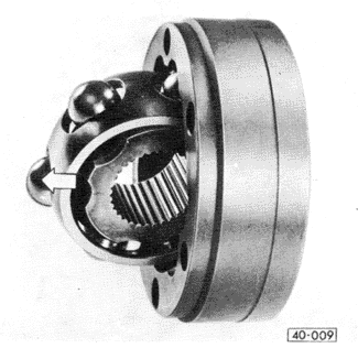
| 1. | With the CV joint removed from the drive axle as described above, mark the relative positions of the hub, the cage, and the outer housing. |
| 2. | Swivel the cage and hub as shown in Fig. 5-12 to remove the balls one at a time. Keep track of the removed balls so that they can be reinstalled in the same relationship to each other and to the marked hub and cage. |
| Fig. 5-12. | Hub and cage of outer CV joint swivelled for removal of balls. Notice mark on outer housing. Similar marks should be made on ball hub and cage. |

|
| 3. | Remove the hub and cage as a unit, turning them so that the two large rectangular openings in the cage are positioned as shown in Fig. 5-13, and remove the hub and cage. |
| Fig. 5-13. | Large rectangular openings in cage (arrow) in position for cage and hub removal. |

|
| 4. | Remove the hub from the cage. Turn the hub so that one of the splines is in line with one of the large rectangular openings in the cage. See Fig. 5-14. The hub now has sufficient clearance to be tipped out of the ball cage. |
| Fig. 5-14. | Hub in position for removal or installation. Rectangular opening just accommodates spline of hub. |

|
| 5. | Clean and inspect the joint for galling, pitting, and other wear or damage. Replace any joint that is worn or damaged in these ways. |
Assembly of the outer CV joint is the reverse of disassembly. Thoroughly coat all parts with molybdenum disulfide grease, and pack the joint with approximately 45 grams (1 1/2 oz.) of the grease. This is half the total amount required for one CV joint. Make sure that the markings made on the housing, hub, and cage during disassembly line up. Install the joint on the drive axle as described in Removing and Installing Constant Velocity Joints. Finish packing the joint with another 45 grams of molybdenum disulfide grease.
To disassemble inner CV joint:
| 1. | With the CV joint removed from the drive axle as described above, mark the relative positions of the hub, the cage, and the outer housing. |
| 2. | Pivot the hub and cage 90° to the housing, as shown in Fig. 5-15, and then push it out of the housing. |
| Fig. 5-15. | Inner CV joint hub and cage with balls being separated from housing. Pivot hub and cage until perpendicular to housing, then push in direction indicated by arrow. |
|
| 3. | Remove the balls one at a time. Keep track of the removed balls so that they can be reinstalled in the same relationship to each other and to the marked hub and cage. |
CAUTION-
The cage, housing, and balls are precisely matched during manufacture. When disassembling more than one joint, do not intermix components between joints.
|
| 4. | Rotate the ball hub into the position shown in Fig. 5-16. The ball grooves on the hub must be in line with the outer edge of the cage. The hub now has sufficient clearance to be rotated out of the cage. |
| Fig. 5-16. | Hub being removed or installed. Arrows indicate alignment of hub ball groove with edge of cage. |

|
To assemble inner CV joint:
| 1. | Clean and inspect the joint for galling, pitting, and other wear or damage. Replace any joint that is worn or damaged in these ways. |
| 2. | Thoroughly coat all components with molybdenum disulfide grease, and install the hub in the cage as illustrated in Fig. 5-16 above. |
| 3. | Install the balls in the cage, as shown in Fig. 5-17, using the adhesion of the molybdenum disulfide grease to hold the balls in place. |
| Fig. 5-17. | Balls being installed in inner CV joint cage and hub. |

|
| 4. | Insert the hub and cage with the balls into the outer housing. |
CAUTION-
The chamfer on the inner splines of the hub (visible in Fig. 5-17) must face the drive axle and the larger diameter side of the outer housing.
|
NOTE-
Align the components so that when the hub and cage are rotated into place, the widely-spaced grooves in the hub will line up with the widely-spaced grooves in the outer housing (a), and the closely-spaced grooves in the hub (b) will line up with the closely-spaced grooves in the outer housing, as shown in Fig. 5-18.
|
| Fig. 5-18. | Inner CV joint hub and cage positioned for assembly in outer housing. Wide grooves in housing (a) mate with wide grooves in hub. Narrow grooves in hub (b) mate with narrow grooves in housing. Arrow indicates direction in which hub and cage assembly is turned to install. |

|
| 5. | Pivot the hub and cage, as shown in Fig. 5-19, until the balls align with the grooves in the outer housing. |
| Fig. 5-19. | Hub being rotated within cage to align balls with grooves of outer housing (arrows). |

|
| 6. | When the alignment is correct, press on the cage as indicated in Fig. 5-20 until it swings into place. |
CAUTION-
The CV joint should go together firmly but smoothly. Heavy force should not be required. If in doubt, start over and recheck the alignment. A joint which is forced together incorrectly may not come apart again.
|
| Fig. 5-20. | Balls being engaged in grooves of outer housing. Apply only hand pressure at point indicated by arrow. |

|
| 7. | Check the operation of the joint. The hub should be able to move smoothly throughout its entire range of travel. |
| 8. | Pack the joint with 90 grams (3 oz.) of molybdenum disulfide grease, using 2/3 of the grease on the outer side of the joint, and the remaining 1/3 on the other side. |
|