Air Flow Sensor
The air flow sensor measures all the air being drawn in by the engine. Air flows past the air flow sensor plate and the plate is lifted, in turn lifting the control plunger in the fuel distributor to meter the fuel. The sensor plate and its cone-shaped venturi are carefully designed to achieve the proper balance of air flow and fuel metering for all flow rates from idle to full throttle. If the sensor plate is off-center or binding, or the lever has too much resistance, the fuel distributor cannot respond properly to the air flow sensor.
To check and adjust:
| 1. | Remove the rubber intake air boot from the top of the air flow sensor. On cars equipped with a protective air flow sensor screen, remove the screen. |
| 2. | Disconnect the coil wire from the center tower of the distributor cap and connect it to ground, using a jumper wire if necessary. Actuate the starter for approximately 10 seconds to pressurize the fuel system. |
| 3. | Using a magnetic tool, lift the sensor plate slowly to check that the resistance, due to fuel pressure resisting movement of the control plunger, is uniform throughout the entire range of travel. Move the sensor plate quickly back to its rest position. There should be no resistance. |
| 4. | If the sensor plate binds as it is moved through the air cone, loosen the center bolt and center the sensor plate. Push down on the plate lightly to check that it is correctly centered in the air cone. |
| 5. | If the sensor plate is hard to move or moves with uneven resistance, remove the air flow sensor from the air filter housing. Clean and lubricate the sensor plate lever pivot so that it moves smoothly. |
| 6. | If the resistance encountered in moving the sensor plate is caused by a binding control plunger, remove and clean the plunger as described below in Fuel Distributor. If it still binds, replace the fuel distributor. |
CAUTION-
There may be a small spring on top of the control plunger. Remove the plunger carefully to avoid losing the spring.
|
NOTE-
Fuel distributors cannot be serviced. Due to the precision fit required, faulty control plungers cannot be replaced separately.
|
| 7. | Reinstall the rubber intake air boot, reconnect the coil wire, and run the engine until it reaches normal operating temperature. Then ground the coil wire and pressurize the fuel system as described in step 2. |
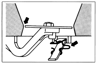
| 8. | Remove the rubber boot and check the height of the sensor plate. At rest, the front edge of the plate should be aligned with the narrowest point in the venturi as shown in Fig. 5-3. Adjust the height by bending the spring clip below the plate. |
| Fig. 5-3. | Correct air flow sensor plate rest position Front edge of plate (left arrow) should be neither above nor more than 0.5 mm (.020 in.) below narrowest point of venturi cone. Adjust height by bending wire spring stop (right arrow). |

|
| 9. | Reinstall the rubber boot and, if applicable, the air flow sensor screen. The word "oben" on the screen faces up. Use care when installing the rubber boot to avoid crushing the screen. |
|
