5.3 Side Mirrors
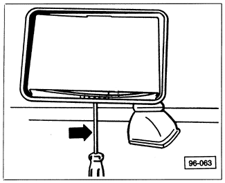
Two types of mountings are used for the mirror glass on side mirrors. On 1985 to 1987 models, the mirror glass is held in place by a locking tab. On 1988 and later models, the mirror glass is press fit into the housing. Fig. 5-20 and Fig. 5-21 show the two types of mounting. Before assuming that the motor on electric remote-control heated mirrors is faulty, check the electrical circuit as described in ELECTRICAL SYSTEM.
| Fig. 5-20. | Side mirror glass on 1985 to 1987 models being removed. Insert screwdriver to engage detent on locking tab and push screwdriver in direction of arrow. |
|
| Fig. 5-21. | Side mirror glass on 1988 and later models being removed. Insert tool behind glass and pry in direction of arrows to pop glass out of mounting. |

|
WARNING-
Wear eye protection. The mirror glass may shatter.
|
To remove manual remote-control side mirrors, first remove the interior door trim panel and protective liner as described in 5.1 Door Assembly. Remove the locknut shown in Fig. 5-22. Pry the trim cover loose and remove the mounting screws. Lift the mirror away from the door, guiding the cable through the door. Installation is the reverse of removal.
| Fig. 5-22. | Exploded view of manual remote-control side mirror on 1985 to 1987 models. 1988 and later models are similar. |

|
To remove and install electric side mirrors:
| 1. | Remove the mirror glass by using a screwdriver to turn the detent through the bottom opening of the mirror. See Fig. 5-20 above. Hold the mirror still. Disconnect the electrical connectors. |
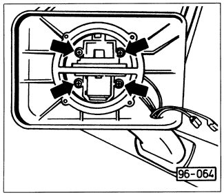
| 2. | Remove the screws from the motor assembly as shown in Fig. 5-23, then disconnect the electrical connectors and remove the motor. |
| 3. | Pry the mirror switch from the inside door panel and remove the connector and the switch. |
| Fig. 5-23. | Electric motor mounting screws to be removed. |
|
| 4. | Remove the interior door trim panel and protective liner as described in 5.1 Door Assembly, then disconnect the electrical connectors shown in Fig. 5-24. |
| Fig. 5-24. | Electrical connectors (1) behind door trim panel to be disconnected. |

|
| 5. | Pry the trim cover from the mirror housing, remove the mounting screws, and remove the mirror housing while guiding the wires through the mirror housing. |
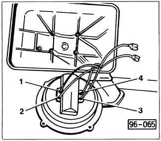
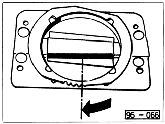
| 6. | Install the mirror in reverse order. Connect the motor wires as shown in Fig. 5-25. Turn the mirror detent in the direction shown in Fig. 5-26 until it contacts the stop, connect the electrical wires, then place the mirror in the mirror housing and turn the detent in the opposite direction to lock it in position. |
| Fig. 5-25. | Wire connections to mirror motor. Motor is marked with numbers. Connect blue wire to 1, brown wire to 2, white wire to 3, and black wire to 4. |
|
| Fig. 5-26. | Mirror detent being pushed to its stop prior to mirror installation. |
|
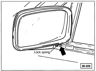
The mirror housing on 1988 and later models can be repositioned if the adjustment range of the mirror glass is inadequate. To reposition the housing, push it forward on its mount until the lock grooves, shown in Fig. 5-27, are visible. Using a screwdriver, lift the lock spring and, while keeping the spring raised, reposition the housing. When the spring is released, the housing will lock in position.
| Fig. 5-27. | Mirror housing on 1988 and later models showing lock grooves (arrow) that are revealed when housing is pushed forward. |
|
|


